


Fuselage - Cabin
Drilled one F-746, attached nutplates, and cleco'd on the FWD top skin.
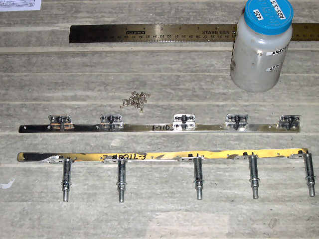
 | Drill one of the F-746 engine control brackets per the plans, then match-drill it to the F-7105A subpanel. |
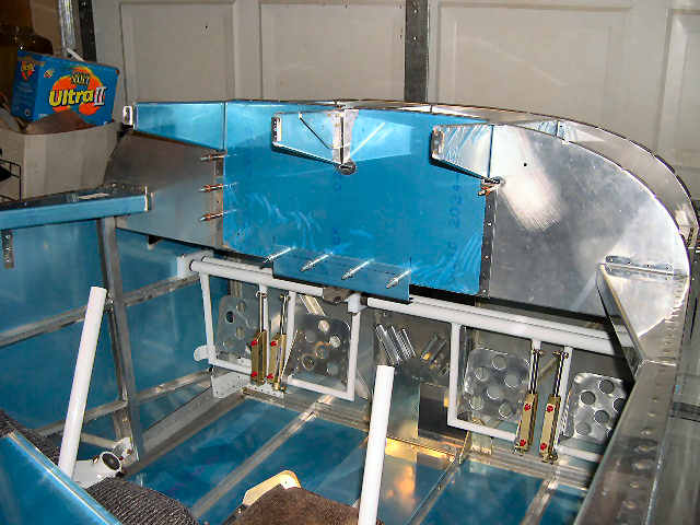 | F-7105A subpanel back in place. Interesting note, the instructions say to cleco the center rib to the firewall, but the FW and the rib don't have any holes. We can't drill the holes until the top skins are cleco'd on. |
 | Next step is to cleco on the top FWD skin, so I decided to go ahead and rivet the nutplates to the ribs and the F-7103B-L/R attach angles, first. I held off attaching them earlier, because I thought the nutplates might interfere with the rivets in the top skin, but it looks like they'll be ok. |
 | Cleco'ing on the top skin. Those clecos in the F-7105A subpanel are a pain. Make sure the clecos go into the subpanel, which has to be pushed into place. Also, I cleco'd on the F-7103B-L/R attach angles, before bending the skin into place. |
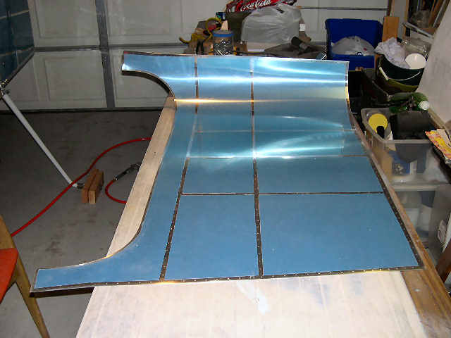 | After I took the last picture, I tried to cleco the top skin down to the fuselage sides and had a little problem. The top skin is .032 and it is a little stiff to push down, so I decided to pre-bend the top skin to make this easier. Of course, this meant I needed to deburr the top skin to prevent cuts and possible stress cracks. In this picture, we are half done with the pre-bend. |
 | Pre-bending helped a lot. It still takes a bit to pull the top skin down to the bottom holes in the longerons, but pre-bend is definitely the way to go. Of course, pre-bending will probably make the dimpling a little harder to do. I think I'll wait till next weekend to match-drill this. |
 | That's a lot of clecos. I had to get out the pneumatic cleco gun, again. |
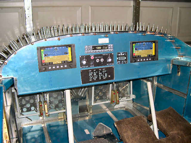 | Since we have the panel in place, we might as well see what it's going to look like with the instruments in place. So, this evening I spent a few hours (again, not logged) going to a few of my favorite websites and downloading pictures of the avionics that I plan to install. I printed full-size pictures of everything, glued them to some card stock, and this is what it all looks like. |
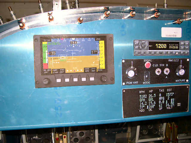 | Up close. And don't ask me why I have the engine monitor on the bottom with the engine controller above it. Obviously, this is not right. |
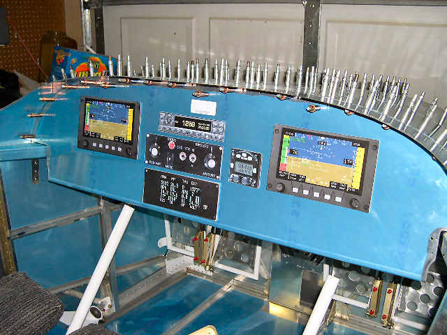 | View from the right side. You can spend all the time you want moving things around a computer screen, but you really need to put the full-sized cutouts on the real panel. This lets you see what's behind each cutout. The panel on the computer screen doesn't show that the ribs angle downward, which can block an instrument that protrudes behind the panel. |