
I am using capacitive fuel senders, but most fuel gauges and EIS boxes do not support capacitive fuel senders. I can either buy expensive gauges, expensive converters, or design my own. So, design my own, it is.
One other reason to design my own gauges/converters is to solve the problem with different types of fuel. There was a big todo with the capacitive fuel senders on the Subaru list a few years ago. Apparently, a few builders flew back home after Sun-and-Fun, and they had severe inaccuracies with different mixtures of MOGAS across the country.
The Subis can run either MOGAS, or 100LL. By law, the 100LL is supposed to be consistent across the country. However, with MOGAS, some states add alcohol, and some do not, or they add it at different concentrations. The dielectric properties of the fuel varies based upon the amount of alcohol added to the fuel. This, in turn, causes the capacitance to change, which causes the fuel gauges to show different values for the same quantity of fuel.
The pilots who were reporting these problems basically said the capacitive senders were unusable for anyone wanting to use MOGAS, unless you refueled from the same pump all the time. Other builders pointed out that even this would not solve the problem, because the quantity of alcohol used in fuel varies throughout the year. The concensus was that you should avoid the capacitive senders.
I didn't say anything at the time, because I didn't have any real experience with the capacitive senders. However, being a software guy, I suspected the problem was not with the capacitive fuel senders, but rather with the converters.
The capacitive senders are two large aluminum plates held apart by insulators. The capacitance of a capacitor varies with the surface area of the plates, the distance between the plates, and the dielectric constant of the substance between the plates. Since the surface area and the distance between the plates never varies, the only variable is the dielectric. When the tanks are empty, the dielectric is air, and when the tanks are full, the dielectric is fuel. Between empty and full the dielectric is a combination of fuel and air. As fuel is added or removed the capacitance varies.
This variance can be measured and converted to fuel quantity. However, you cannot just hook the capacitive senders up to normal fuel gauges. Normal fuel gauges measure the voltage across a resistor. With the capacitive senders you would always show the same voltage, and hence the same level of fuel. Our first task is to either design our own fuel gauges, or design a converter to convert the capacitance into voltage levels that are equivalent to the resistive fuel senders.
As stated before, if you use MOGAS instead of 100LL, the capacitance will not be the same when the tanks are full, or any other level other than empty. Therefore, the second task is to come up with a solution that allows us to display reliable fuel quantities no mater what type of fuel is used.
So, how do I propose to solve these two problems? Well, being a software weenie, I will use a microprocessor, of course. Since I already have a controller board to control the LED strobes, it makes sense to make this controller board do a little more than blip three LED circuits once-a-second. In fact, a microprocessor is overkill for that application. I could have easily done this with a simple timer circuit, and that is exactly what I did a few years ago when I originally played with the strobes. But I wanted to do a few other things with the controller board, and fuel gauges for the capacitive senders would be first on the list. Of course, I will have at least one engine monitor on board, and showing a fuel quantity of zero would be very disconcerting. Therefore, I will also use the controller board to output voltages that are equivalent to what the resistive fuel senders would output.
There are two ways to mearsure capacitance that immediately came to mind, both of which do essentially the same thing, they convert capacitance to frequency. One method, is to use the capacitor to control the frequency of an oscillator. As the capacitance changes, the frequency changes, and the frequency can be measured by counting pulses, or by using a frequency to voltage converter.
That is what Jim Weir did with his circuit for capacitive fuel gauges. His is a discrete solution that is not able to handle the second requirement of being able to deal with different fuel types. Also, it is a little more complex than what can be done with a microprocessor with A-to-D inputs. A number of guys on the VansAirforce RV forums had this same idea.
Actually, now that I think about it, Jim's descrete circuit could probably solve the problem with different fuel types, by simply adjusting the end point calibration when new fuel is added. May want to look into this.
Anyway, my idea was to use a large resistor in line with the capacitive senders, and measure the amount of time it takes to charge the capacitive senders to a known voltage. In doing a little research into A-to-D and how to measure capacitance, this was one of the methods suggested, so I was not alone in my thinking. It turns out this is an extremely simple circuit, if you have a micro processor to start the charging and do the timing. The circuit looks something like the following:
With this circuit, solving the problem with different fuels should be fairly easy, as long as we have calibrated the fuel gauges properly. Calibration is a process of adding fuel one gallon at a time, and having the controller note the capacitance for each gallon added. During normal operation, the controller finds the closest fuel level for the current capacitance, does any interpolation when the capacitance falls between two levels, and displays the fuel level. The controller, also, generates the correct voltage for the current fuel level and sends that to the engine monitor or standard fuel gauges.
When the tank is topped, the controller needs to calculate the ratio between the calibrated capacitance when the tank is full, and the current capacitance. This ratio can be used to adjust the fuel level displayed for the current capacitance as the fuel is used. No matter what type of fuel is added, the controller should be able to display the correct fuel level. This does require the pilot to enter the current amount of fuel, but it appears that several engine monitors already require this. When power is applied, the controller will alert the pilot to set the fuel level.
That's all well-and-good in theory, but how do we know if this will actually work? Looks like I need to do some sort of prototype to test out theses ideas, but with an airplane to build, who has time to do a prototype for capacitive fuel gauges? Well, for the past three months, I have not worked on the airplane. This was mainly due to the saga of the "rats in the wings", again, but the cold weather had a lot to do with it, also. During that time span, I did manage to do a little prototyping on the capacitive fuel gauges controller. The following pictures show some of the work that I have done:
 |
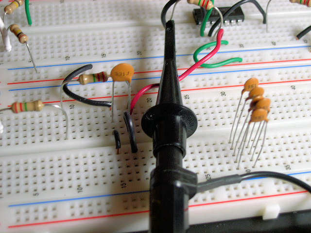
Here's my prototyping setup: Zilog Encore F082 emulation module board on the left, my strobe controller board driving a 20x4 LCD module on the right, and the capacitance measuring circuit in the middle. It turns out my capacitance measurement circuit is a little more complex than the picture above. It looks like the capacitance of the A-to-D input is higher than the senders, so it was nearly impossible to detect the small changes when I simulated fuel being added. I added an opamp between the capacitor and the A-to-D input, and this seems to do the job. |
 |
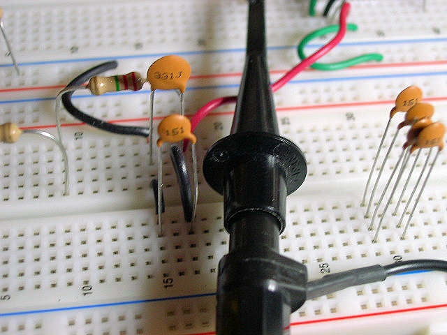
Jim Weir's article said the capacitance of his senders when the tank was empty was around 350pf, and the capacitance when it was full was around 700pf. I am not sure if my tanks are similar to his, but just for testing, I am using a 330pf capacitor to simulate an empty tank. |
 |
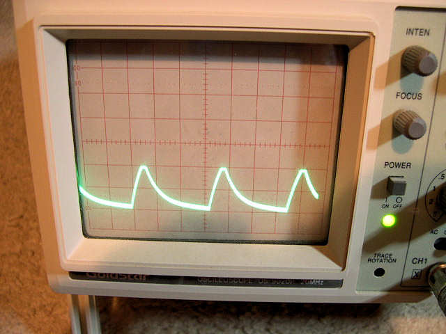
This is the scope output for the simulated empty tank. Note, that we have 4 pulses for an empty tank. |
 |
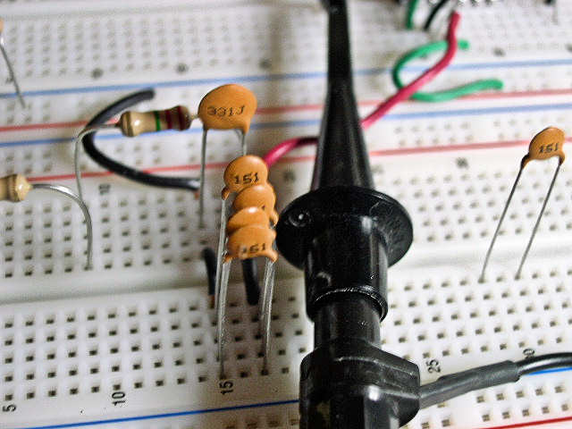
I had 150pf capacitors available, which for Jim's tanks would be about half-full, but just for tesing, I'll call this 1/4 tank. |
 |
Scope output for the simulated 1/4 tank. More capacitance means longer to charge, so we now only have 3 pulses in the same amount of time. |
 |
We'll call two 150pf capacitors half-full. |
 |
Scope output for the simulated half-tank. Yeah, it does not appear to have changed much. Sometimes adding a capacitor does not have much effect. Not sure if this is a problem with the individual capacitors, or more likely, a problem with my setup. |
 |
We'll call three 150pf capacitors 3/4 full. |
 |
Scope output for the simulated 3/4 full. There we go, down to two pulses. |
 |
All four 150pf capacitors represent a full-tank. |
 |
Scope output at simulated full-tank, and we see a little less than two full pulses. |
Ok, I can measure capacitance, so my idea works. I just need to try this with a real tank of gas, which probably ain't gonna happen anytime soon. I need a board that I can take outside, the right connectors, and a little more tweaking of the circuit. I am using a 20x4 text LCD module, but I have a graphics LCD module that I want to play with, plus, I need to layout another board. Probably a few hundred more hours before I am done. Note, none of this time is accounted for in the log.
Stay tuned...