I have decided to build my own nav and strobe lights using SuperBrite LEDs. Initially, I looked at building my own lighting system due to the cost. The lighting system on a typical RV costs about $900. This includes $750 for the nav and strobe lights, plus $150 for the landing and taxi lights. This seems like a lot of money for a relatively simple system, so I started looking into alternatives.
I liked the idea of using LEDs because they last a long time and they do not draw a lot of current. However, SuperBrite LEDs are relatively expensive and it takes a lot of them to duplicate the amount of light required by the FAA. SuperBrite LEDs run about $1.50 a piece in small quantities and around $1.00 to $1.20 for quantities of 100. Whelen is selling nav lights with 10 SuperBrite LEDs. So, even at $1.50 a piece, and using 15 LEDs instead of 10, I can build a light that is still a lot less than the $70 that Whelen charges for their incandescent nav light.
The nav light is a no-brainer, but what I really want is a SuperBrite LED Strobe light. A normal strobe light requires a 350 volt power supply that costs $400 for a 3-strobe system needed by an RV7. The real problem is the 350 volt pulse that goes to the strobe lights 40-60 times a minute. In my last airplane, the strobes created a lot of noise in my radio, so I never turned them on. Note, that strobes are required by the FAA, day and night, but you can turn them off if they reflect off the clouds. Hey, they reflected off my ears, that's close enough for me.
With LEDs, the pulse will be 12 volts instead of 350, which should get rid of any noise problems. This means I won't have to run two separate conduits in the wing (one for comm, and one for lights). Although, I might do it anyway, just to be safe. If things work out ok, the LEDs will use less power, save weight, and get rid of the strobe noise.
The problem with the strobe lights is that the regs require a fairly significant high intensity light pulse all around the aircraft. Most of the energy has to be concentrated in a narrow band along the horizontal axis, but the total coverage has to be 75 degrees above and below the aircraft. This will take a lot of LEDs to cover the whole area. Whelen is doing this with what looks like either 36 or 48 LEDs in a rotating beacon replacement. I am going to try it with 60 LEDs.
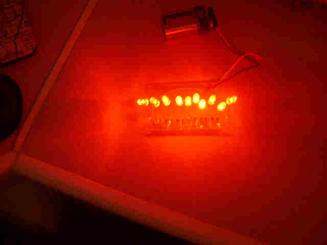
Anyway, I ordered some LEDs and did some experiments. Here is my first proto board with red LEDs:
Each LED is supposed to be 10 candelas, so I figured 10 LEDs would give off 100 candelas. When I measured one LED by itself, I saw 10 candelas, but I was only getting about 35 candelas from the whole group. Obviously, they need to be concentrated a little closer together. By the way, these are very bright, even if the light meter doesn't say so. They actually hurt your eyes to look at them. They just aren't projecting the right pattern yet.
I went ahead and did a layout for a PCB that would include both nav lights and strobe lights. I ordered 3 PCBs and 200 more LEDs. We'll see how it goes.
I got my boards in last week and spent one night soldering green LEDs onto one board for the green position light. The green LEDs looked pretty good, and definitely give off the required 40 candellas.
Next, I spent another night soldering on 60 white LEDs for the strobe light. The white LEDs are very bright, but did not give off enough light. My test setup was using two 9-volt transistor batteries to drive them, which is clearly not enough juice. The white LEDs are supposed to draw about 1.5 amps with a 12 volt battery connected. The 9-volt transistor batteries just cannot deliver this kind of current, so I recharged my 12 volt gel-cell that I use for my RC stuff and tried again. This worked a lot better, but the battery still dropped down to 10 volts when I connected the white LEDs.
Here's a picture of the board with all of the LEDs and other parts installed. Note, that the LEDs are off in the first picture, and I bent some of the LEDs to test illumination to the sides of the main axis.
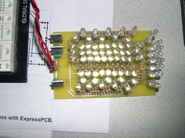

The LEDs are very bright, so I am a little concerned about damaging my camera with everything powered-on and looking straight on. This is a picture from the side, with just the green LEDs turned on. I'm using the 9-volt batteries, so the intensity is way lower than normal.
The next thing that I did was to cobble together a circuit that would blink the white LEDs. I made a simple oscillator using CMOS 4011 NAND gates with some feedback. The right resistors and capacitors will produce a 1 second blink rate with a 50% duty cycle. An aircraft strobe needs to be between 40 and 70 cycles per minute with no less than a 1:75 on/off ratio. The once-per-second flash rate is ok, but the 50% duty cycle needs to be closer to 10% to get a better strobe effect. Anyway, this is just for testing.
With this setup, I am seeing between 800 and 1800 lumens from the green LEDs, which is great, since I only need about 480 to be legal. However, I am only getting about 3000-4000 lumens from the white LEDs, so I need to do some work on the strobes. The strobes need to produce 400 candella (about 4800 lumens).
Right now, I am using 120 ohm resistors on the white LEDs to limit the current to about 30ma each. However, the SuperBrites can safely take up to 100ma for 10ms, so I have a little room to experiment. I will try 56 ohm resistors when I wire up a board using Red LEDs for the strobe. The regs say the strobes can be either Aviation Red or Aviation White, and the Red LEDs are $36/100 while the white LEDs are $120/100 (I have seen them for $109/100). What color would you use? I'm not sure if I can mix red and white.
I haven't updated this page for quite a while, but I have been doing a lot of work on the LEDs. First, I ordered a new Z8 development board from Zilog, so I could develop the code to control the strobes. I said I would never buy anything from Zilog, again. They laid me off two years ago, when they closed-down the Austin design center, and I was a little unhappy with them. Oh, well, things change. I like the Z8 instruction set a lot better than the MicroChip PICs. And now that they finally put flash on the Z8 parts, they are really nice to work with. Besides, the Z8 development kit is only $40. I feel like I am taking advantage of them.
Anyway, I used the development board to prototype a strobe flasher and everything worked great, so I laid-out a board for the strobe controller. I am using Express PCB to design and build all of my boards. For $60 (including shipping), you get three 2.5" x 3.5" board in three days. Plus, they supply you the schematic and layout software for free. And, when Airborne Delivery says they left your package on the doorstep, but there is no package, Express PCB will ship you three new boards in three days without any hassle. These guys are really great!
Here's a picture of the strobe controller board:

The Z8 is really easy to use. You just need a crystal, a few capacitors for the clock, reset, and A-to-D input lines, a pull-up resistor for the reset line, 3.3 volts, and you are ready to control something. The small connector on the left is for connecting the OCD (on chip debug) interface which allows you to debug and program the parts in circuit. The OCD controller is part of the $40 development kit.
On this board, the Z8 drives an 74HC00 (quad nand gates), which drives a ULN2074B (Transistor Array), which drives the LED strobe board. You could just as easily connect the 7400 to TIP120 transistors to drive up to 10 amps. There's also a 5v regulator for the 7400, and a variable regulator for the 3.3v needed by the Z8. You can't get much simpler.
BTW, this is the first time that I tried to use a non-dip processor. The Z8 is a 28-pin SOIC, which is impossible to plug into a prototype board without an adapter. I priced the adapters at Digi-Key, and they are about $80 each, so it is cheaper to actually layout a board and fab it at Express PCB and get 3 adapters for $60. I didn't have any problems soldering the SOIC to the board. Although, I do have 3 other Z8 cpus that are SSOC's and way too small for me to solder. The Z8 CPUs are $4-$6 at Mouser Electronics.
After I got the controller working, I figured out that in order to turn the LED strobes on and off using the drivers that I had chosen, I could not use a common ground between the position LEDs and the strobe LEDs. So, I needed to modify the LED boards slightly. With the first boards I was able to cut the grounds and use a haywire to fix the boards. I also decided to remove the regulators from the LED board and put them on a separate driver board inside the wingtips. The regulators are ugly, and take-up a lot of space. Also, it looks like I will need a heat sink for the position light regulator. This allowed me to re-layout the board and add more LEDs for the strobes. The next board will have 96 LEDs for the strobes instead of 60.
A HW guy at work explained to me why my original method of driving the strobes would not work with the drivers that I had chosen. He also pointed out to me that I could drive more than one LED per resistor, if I reduced the resistance. And, he explained to me why I should be using 5v regulators on the LED boards instead of 8v regulators. It's nice to have professional consultation readily available--thanks Hanan.
Before ordering new boards, I decided to see if I could get some more light out of the LEDs for the strobes. So, I spent several nights taking measurements with different resistor/LED combinations. I didn't do enough experimentation before I wired up the first strobe board, and the light output was lower than anticipated. This was due to too high of resistor values for the strobes. Although, the green LEDs seem to be just about right.
Here's a picture of my measurement setup:
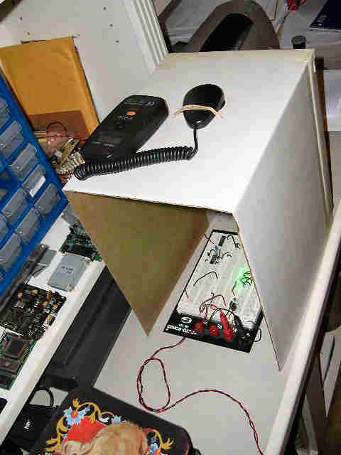
Not fancy, but it works. The cardboard box holds the light meter exactly 1 foot above the LEDs. One foot makes the math simple (12.57 lumens = 1 Candella). I haven't tried to do measurements at different distances (you need to use the square of the distance times the reading).
After trying dozens of resistor/LED combinations, I found that the green LEDs meet their specs, the white LEDs are close to spec, and the red LEDs fall about 20% below their specs. I suspect that my light meter is not as sensitive to the red light, which makes it read a little low. I also found that at 30ma, the LEDs are about 50% brighter, and nearly twice as bright at 50ma. I was not sure how much extra light I would get above 20ma before I did the measurements.
At 100ma, it is too hard to get a good reading. The LEDs and resistors tend to get too hot, and the light output actually starts going down as the parts heat up. I feel pretty safe driving the LEDs at 30ma, continuously, and pulsing them at 50-100ma.
Anyway, I have enough combinations to choose the correct resistors to drive the LEDs for the different configurations. Note, that since each color drops a different voltage for a specified current, the LED/resistor combinations are different for each configuration. I plan on driving the nav light LEDs between 20 and 30ma, and the strobe light LEDs around 50ma.
With this info, I wired up the second LED board with red position LEDs and white strobe LEDs, using 12ohm resistors for every two white LEDs, and one 82ohm resistor per red LED. Here's a picture of the two LED boards that I have currently wired-up. One has green position LEDs and one has red position LEDs. The strobe controller is flashing the white strobes on the red LED board. The red LEDs are not on because they are drawing 500ma, and I did not have a heat sink for my regulator.
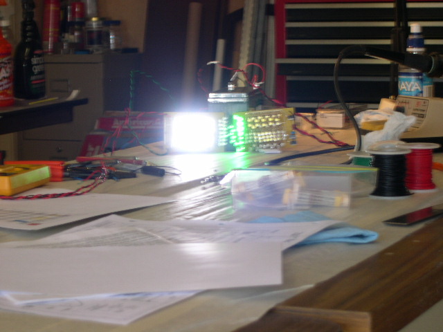
Note, that this board only has 50 white LEDs because I ran out. However, I did a quick measurement of the strobe lights on this board, and it is putting out the full 400 candellas. I just need a few more LEDs so I can point the extra LEDs in different directions to get the required coverage.
I have a new layout for an LED board with 96 strobe LEDs and 16 nav LEDs. With that many strobe LEDs, it will be hard to supply them with enough current using my current strobe controller board. However, before I fab another LED board, I need to wire-up my last LED board using red LEDs for the strobes. The red LEDs are not as bright as the white LEDs, but they are 1/3 the cost.
After looking where the tail light goes on the rudder fiberglass tip, I figured out that there is no way to use my LED Strobe/Position board, as is. The board is too big to hang off the end of the rudder, so I have decided to improvise a little. First, the tail light will go out the back of the fiberglass tip, just like a normal strobe/tail light. However, I am going to have to put the strobes on each side of the rudder fiberglass tip. I will have to build a vacuum box and fabricate a clear plastic cover for the LED strobes. This is getting to be a big project.
I decided to try and wire a bundle of LEDs without a board to see how it would fit into the end of the rudder fiberglass tip. Since I am out of white LEDs, I used Red LEDs for the test bundle. I wired the bundle as follows:


This bundle is kind of a mess. I need to take a little more care when I bundle the LEDs all together. However, it does put out the correct level of light in all the right directions. This looks very nice from a distance.
After viewing the LEDs from across the street, I was very happy with the looks of the light. It emits a nice round light, as opposed to the LEDs on the PCB board, which has an elongated pattern. These looked so good, that I am considering using wire bundles for all of the position lights. This would also give me more room on the LED board for strobe LEDs.
I'm still working on this...